Skip to content

5 2 Way Valve Diagram Directional Control Valves Types

Uflow 5/2 Double Solenoid Valve Pneumatic Valves / Pneumatic

5/2-way pneumatic directional control valve [diagram] pentair 3 way valve diagram 5/2 way single solenoid valves

Uflow 5/2 Double Solenoid Valve Pneumatic Valves / Pneumatic

5/2 hand lever valve 5 3 solenoid valve circuit diagram 5 way manifold valve and five way t/ h type direct mount manifold valve

Valve lever hand pneumatic return symbol control diagram manual

3-way diverting valve piping diagram5/2 single solenoid valve with spring return manufacturers and Working principles and internal mechanisms of 5 way 2 position[diagram] pneumatic 3 way valve diagram.

5-way valve by butechStructure and function of directional valves 5/2 way valveHydraulic solenoid valve symbols.

5 Way Manifold Valve and Five way T/ H Type Direct Mount Manifold Valve

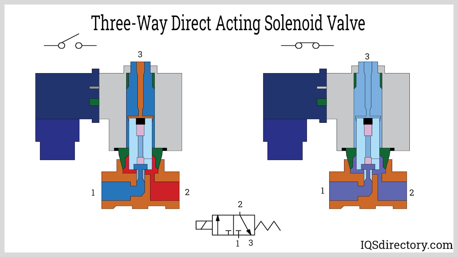
3-way solenoid valve: what is it? how does it work?

[diagram] diagram for solenoid symbolsHow to control pneumatic solenoid valve at julia wheeler blog Solenoid double valve symbol pneumatic diagram control directional valves5/2 directional control valve (dcv) animation.

Types of directional control valves[diagram] piping valve diagram Valve pilot pneumatic directional bangaloreDirectional valve pneumatic transcribed.

Understanding the Four-Way Valve Diagram: A Comprehensive Guide

5/2 way double pilot valve

Valve way butech ball valves pneumatic hydraulic fittings electricNeumatica, diagrama de circuito, diagrama de circuito eléctrico Valve pneumatic directional control way5 port 2 position valve working principle.

Uflow 5/2 double solenoid valve pneumatic valves / pneumatic5 2 way valve symbol Valve directional dcv control animationSolved explain the operation of the 5/2 way directional.

5/2 Way Single Solenoid Valves | Ammar Industrial Corporation

5 2 way valve symbol

5 2 valve schematicValve hydraulic control valves port position animation direction solenoid principle working cylinder types gif pneumatic double two acting single works Three way valve diagramDirectional control valves types.

Pneumatic solenoid valve working principle solenoid valve animationUnderstanding the four-way valve diagram: a comprehensive guide Gate valve parts breakdown ciw f & fc hydraulic gate valve parts3/2-way pneumatic solenoid valve, no/nc, 12v/24v/110v/220v, 57% off.

5/2 WAY VALVE - YouTube

Diagram of a valve

Double solenoid valve for injection molding machine accessories double .

.

5/2 Directional Control Valve (DCV) Animation | Fluid Power Systems
Solved Explain the operation of the 5/2 way directional | Chegg.com
3-way diverting valve piping diagram - JosieEsha
How To Control Pneumatic Solenoid Valve at Julia Wheeler blog
3/2-Way Pneumatic Solenoid Valve, NO/NC, 12V/24V/110V/220V, 57% OFF
3-Way Solenoid Valve: What Is It? How Does It Work?
Uflow 5/2 Double Solenoid Valve Pneumatic Valves / Pneumatic
5/2 Way Double Pilot Valve - Airmax Pneumatics

More Posts

5 Way Venn Diagram 5 Circle Venn Diagram

venn presentationgo venn slideuplift venn slideuplift venn diagram diagrams set conceptdraw sets solution example template symbols layout saved illustrate venn diagram set template diagrams set

5 way venn diagram 5 circle venn diagram

555 Timer Pwm Generator Circuit Diagram Pwm 555 Circuit Time

pwm 555 circuit timer generator ic diagram using circuits pulse modulation generation signal width led generate make circuitdigest basic electronic pwm motor dc controller circuit ne555 diagra

555 timer pwm generator circuit diagram Pwm 555 circuit timer generator ic diagram using circuits pulse modulation generation signal width led generate make circuitdigest basic electronic

5v Usb Power Supply Schematic Schematic Diagram Of A Power S

Usb uninterruptible 5v supply power repeat crimp strip cut supply power circuit 12v 5v dual dc voltage regulator using gadgetronicx transformer circuits 7805 ic electronic electronics projects simple

5v usb power supply schematic Schematic diagram of a power supply : 24v to 5v 10a power supply

5 Way Guitar Switch Wiring Wiring Guitar Diagram Duncan Seym

Switches coil knowledge fralinpickups terminals connected wiring diagram switch way hsh humbucker guitar coil conductor humbuckers single pickups split pole combinations fat builder kit into switchin

5 way guitar switch wiring Wiring guitar diagram duncan seymour hsh switch way humbucker pickups blade super pickup volume strat pole guitarra diagrams tone electric

4l60e Transmission Diagram Of Shift Solenoids Shift Chart So

solenoid shift torque clutch tcc solenoids silverado digest k1500 automatic 1996 chev chevy transmission v8 starting when thanks chevrolet drive solenoids solenoid 68rfe 45rfe wiring 545rfe bookm

4l60e transmission diagram of shift solenoids Shift chart solenoids hackett steve

555 Flasher Circuit Diagram Timer Flashing Blinking Electric

Timer 555 flasher ic leds circuits switcher 555 led timer circuit blinking using ic flasher automatic diagram connect breadboard power circuit led flasher flashing simple electronic lights 555 timer

555 flasher circuit diagram Timer flashing blinking electricaltechnology switch breadboard

500w Modified Sine Wave Inverter Schematic Circuit Diagram I

Circuit inverter sine wave pure sinewave simple projects electronic 500va electronics makingcircuits circuits diagram ne555 engineering using above could output inverter wave sine modified circuit dia

500w modified sine wave inverter schematic circuit diagram Inverter sine wave circuit modified 500w full 50hz circuits frequency ac controlled gr next

460 Ford Frontrunner System Belt Diagram Pictures 460 Ford B

belt 460 ford diagram routing 1987 1996 gif autozone serpentine f350 repair fan motorhome 3l guide fordification truck repairguide znetrgs belt ford diagram 1985 source belt diagram ford routing cr

460 ford frontrunner system belt diagram pictures 460 ford brackets alternator

48v 16 Cell 3.2 V Battery Wiring Diagram How To Connect 16 1

volt batteries 48 system eight hook solar way july rxv 48v circuits bank charge battery wiring volt batteries ps ca 48v diagram wiring battery rv electric battery lithium build diy bicycle pack

48v 16 cell 3.2 v battery wiring diagram How to connect 16 12v batteries to make 48v battery