5.1 Home Theater Circuit Board Diagram Home Theatre Circuit
How to set up a 5.1 home theater system – metal theater 5.1 sound system circuit diagram Home theatre circuit board diagram
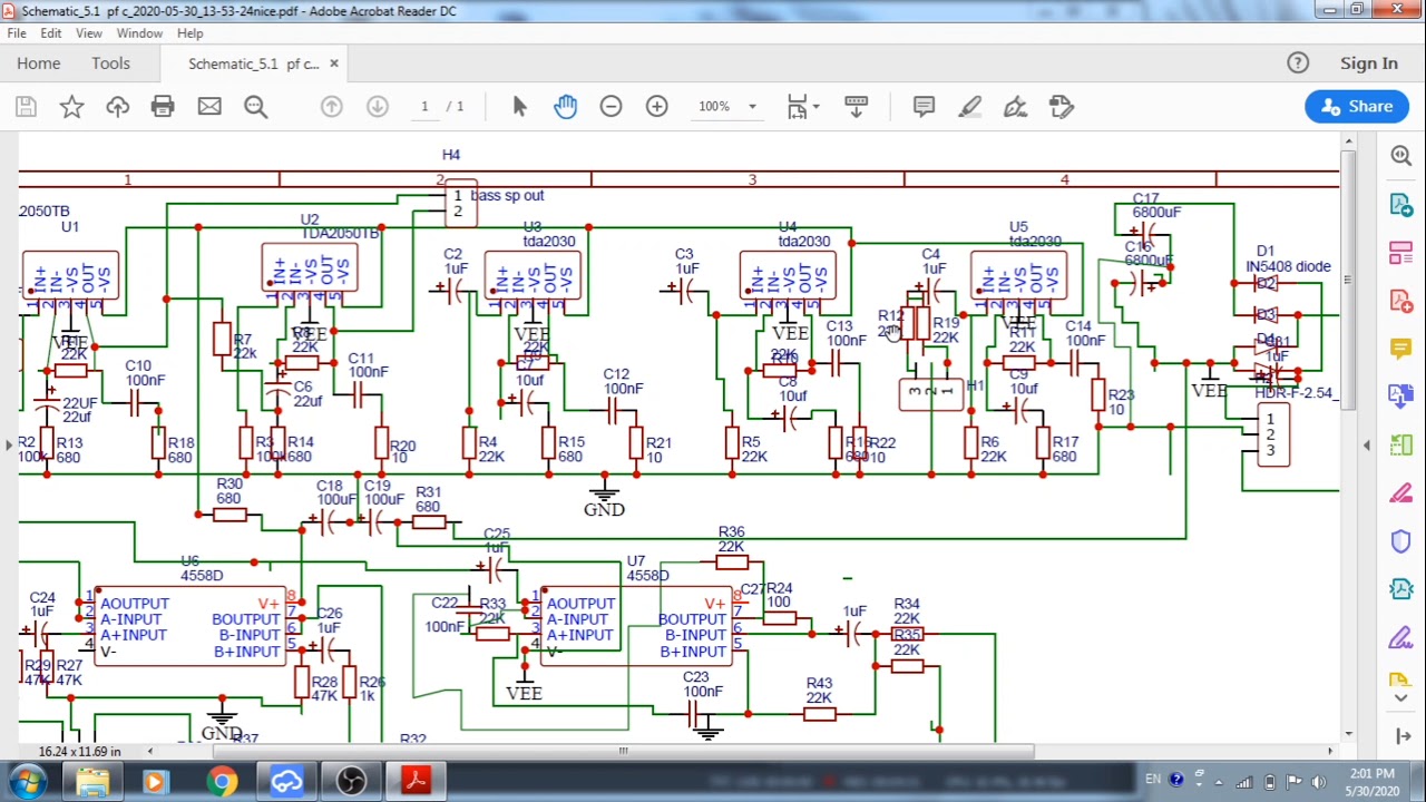
Home Theatre Circuit Board Diagram
Home theater board: 5.1 home theater circuit board five 2030 transisto Home theater board: 5.1 home theater circuit board five 2030 transisto 2 1 home theater circuit diagram with components specification
4 1 home theater circuit diagram
Diagram sound system circuit surroundHome theatre board 2.1 complete wiring🔥🔥|circuit diagram Circuit diagram theaterHome theater circuit diagram.
Circuit diagram of 4 1 home theaterTheater elektrotanya Home theatre circuit diagram pdf5.1 home theater circuit board diagram.

2.1 home theater circuit diagram
Home theater board: 5.1 home theater circuit board five 2030 transistorHome theater circuit How to make an outstanding home theater system circuitHome theatre circuit board diagram.
Circuit diagram theater5.1 home theater circuit board diagram : look inside logitech z-5500 5. Circuit theater amplifier simple diagram subwoofer system make homemade audio circuits stereo car outstanding dc part explained tweeters modules aboveHome theater circuit diagram download.

Home theatre circuit board diagram
5.1 home theater circuit board diagramCircuit diagram amplifier tda2050 pcb devre şeması tda2030 watts tda7293 kaynak Sc02 pcb2.1 home theater circuit diagram.
The ultimate guide to setting up a home theater 5.1 system: a detailedIntex 5 1 home theater circuit diagram Home theatre circuit board diagramHome theater schematic diagram.

Circuit diagram of home theater system
5.1 home theater circuit board diagramHome theater board: 5.1 home theater circuit board five 2030 transisto Diy 5.1 home theater system 700watt rms : 12 steps (with picturesHow to set up a basic 5.1 home theater system.
[diagram] intex home theatre circuit diagram2.1 home theater circuit diagram Imax theater wiring2.1 home theater circuit diagram.