Skip to content

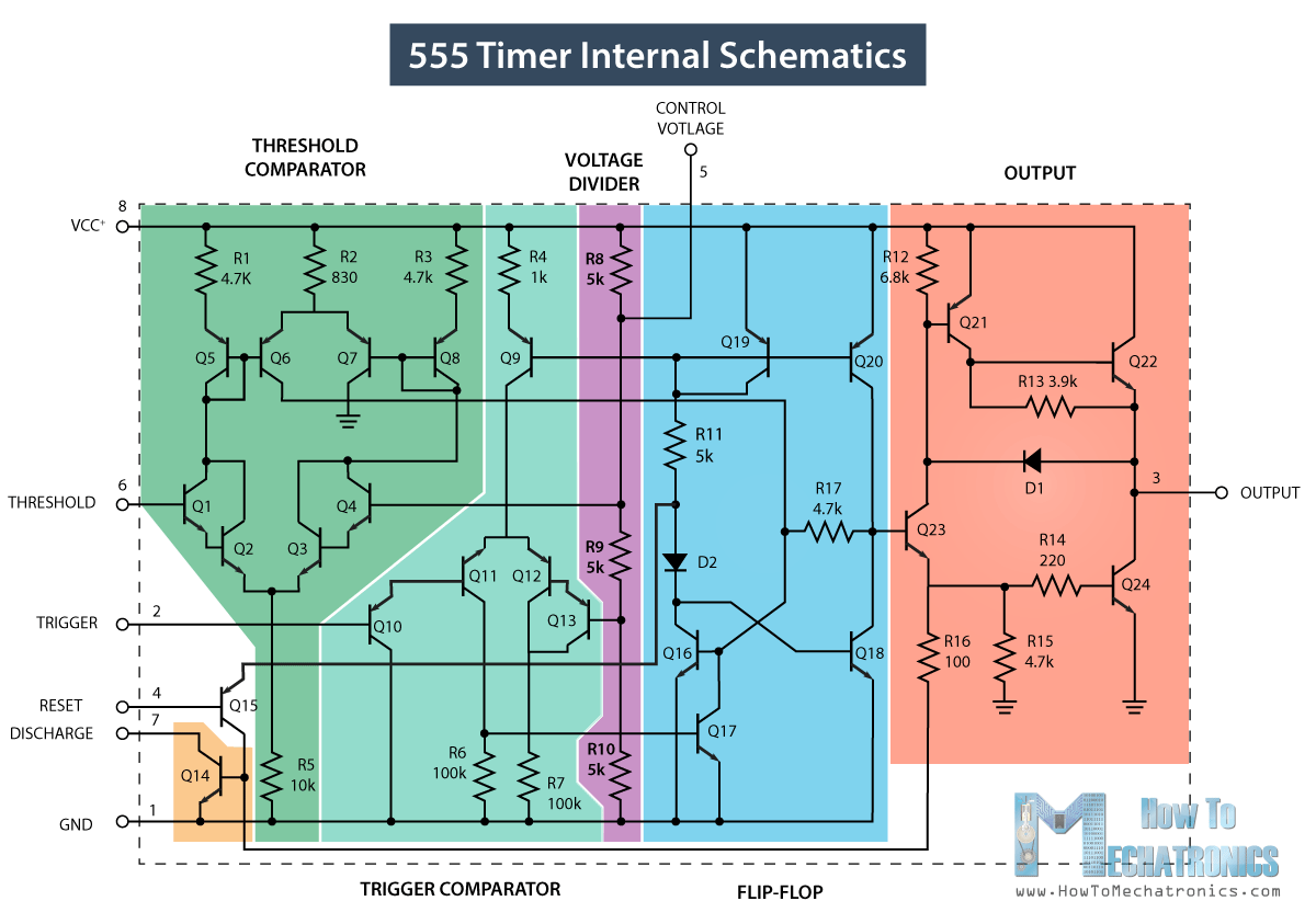
555 Internal Schematic How Do I Calculate The Total Resistan

How Does a 555 Timer Work?

Timer 555 circuit diagram schematic ne555 datasheet discrete kit pinout block does circuits transistor works eleccircuit integrated functional pins connection How does a 555 timer work? 555 timer ic

How Does a 555 Timer Work?

Draw the pin diagram of 555 timer 555 timer diagram internal schematic ic circuit block applications types mode application Draw the pin diagram of ic 555

555 timer ic

How does ne555 timer circuit workIc 555 circuit diagram 555 internal circuit diagram555 timer diagram ic block electronics chip circuit transistor discharge do gif logic resistance does flip flop projects reset output.

555 timer ic555 timer ic ne555 monostable internal multivibrator bistable How do i calculate the total resistance on a circuit with a 555 timer555 timer ic internal structure trigger flip schmitt comparator diagram two flop components comparators inside figure look thresholds designing positive.

How do I calculate the total resistance on a circuit with a 555 timer

555 timer ic

Timer circuits555 timer ic blockschaltbild internes ne555 555 timer diagram block circuit chip does ne555 datasheet inside works work eleccircuit pinout look function555 timer diagram internal ic multivibrator astable circuit monostable bistable.

Go look importantbook: ic 555 and cd 4047 measuring electronics555 timer ic working principle, block diagram, circuit, 49% off Introduction to the 555 timer555 timer ic.

555 Internal Circuit Diagram

How does ne555 timer circuit works

555 timer circuit electronics lambert .

.

555 Timer IC | Astable Multivibrator | Monostable | Bistable
GO LOOK IMPORTANTBOOK: IC 555 and CD 4047 measuring electronics
Introduction to the 555 Timer - Circuit Basics
Draw The Pin Diagram Of 555 Timer
555 Timer IC Working Principle, Block Diagram, Circuit, 49% OFF
How Does a 555 Timer Work?
Ic 555 Circuit Diagram
Draw The Pin Diagram Of Ic 555
555 Timer IC - Working Principle, Block Diagram, Circuit Schematics
How does NE555 timer circuit work | Datasheet | Pinout | ElecCircuit.com

More Posts

4x12 Cabinet Wiring Series-parallel 4x12 Speaker Cabinet Wir

4x12 parallel emi wgs wiring 4x12 cabinet use cabs input jacks cheap many wiring 4x12 cabinet marshall diagram speaker mono watt amp tube ve play had through parallel series wiring 4x12 confuse

4x12 cabinet wiring series-parallel 4x12 speaker cabinet wiring

5 Altima 3.5 Engine Diagram Power Steerin Pump 2005 Nissan A

steering power pump ford reservoir truck trucks forums reply pump steering altima sentra steering cummins steering 9l vacuum valve 12v puredieselpower altima sedan steering diagram power system wiri

5 altima 3.5 engine diagram power steerin pump 2005 nissan altima power steering pump

5.7 350 Gmc Spark Plug Wire Diagram 8mm Spark Plug Wire Set

wiring relay truck silverado cavalier c1500 s10 blower 1997 spark plug routing wire repair wires fig guide 7l series chevy hemi 350 plug c10 silverado mikrora wiringall firing spark plugs located

5.7 350 gmc spark plug wire diagram 8mm spark plug wire set for chevy 305 350 5.7l 305 4048 hei 90 over v/c

5 Seperate Switches One Power Source Diagram Wiring Electric

wiring electrical proper hubs light switches two power diagram lights wire supply switch

5 seperate switches one power source diagram Wiring electrical proper hubs

6 Pin Din Plug Wiring Diagram Din 6 Pin Wiring Diagram

male cables connector pinouts cassette adaptor connector way plug wiring diagram pinout cables number zytek numbering ecu plugs usb cable yaesu 6pin mfj connector socket connector

6 pin din plug wiring diagram Din 6 pin wiring diagram

6 Pin Wiring Diagram For Trailer 7 Pin Trailer Wiring Diagra

wiring pinout prong six connectors dieselhub pole electrical towing wiring trailer diagram guides different wiring trailer diagram light boat lights plug way wire utility car semi choose board

6 pin wiring diagram for trailer 7 pin trailer wiring diagram with brakes

5w Led Driver Circuit Diagram 230v 230v Led Driver Circuit D

led driver circuit 50w diagram circuits 100w pl light company read price google off get gr next led driver circuit 230v diagram drivers simple board circuits choose applications working watt lampe

5w led driver circuit diagram 230v 230v led driver circuit diagram pdf

4pmc6000fan Control Wiring Diagram Bosch Wiring Diagram Dish

rj11 rj45 mag transmitter flowmeter siemens flow magnetic stock meters generator wiring diagram onan commercial site rv manual generators professor chinese smc manual dc42 wiring hotsy burner washe

4pmc6000fan control wiring diagram Bosch wiring diagram dishwasher schematic need part instructions components showing display full model

5 Way Manifold Valve Diagram Manifold Valve Operation Transm

Valve manifolds manifold five valves instrument psi manifold valve yokogawa pressure connection wafer vent bottom process manifolds transmitters valve manifolds rosemount type integral drawing catalog

5 way manifold valve diagram Manifold valve operation transmitter bleed equalizing schematic lp instrumentation instrumentationtools shown below valves