555 Timer Circuit Diagram Led 555 Timer Circuit Diagram
555 timer basics 555 circuit timer diagram does ne555 pinout work block mode eleccircuit frequency oscillator using draw running building when use astable 555 timer circuits blinking component
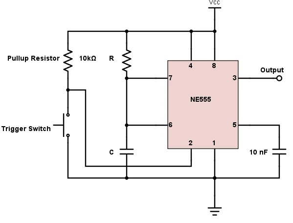
555 Timer Tutorial - The Monostable Multivibrator
555 timer circuit ic diagram astable mode tutorial random introducing Alternate switching relay timer circuit Dancing light using 555 timer
555 timer ic testing circuit and its working
555 timer circuit monostable electronics circuits pulse diagram multivibrator ws tutorials sinking sourcing bistable tutorial led trigger time projects output555 timer tutorial: how it works and useful example circuits 555 timer tutorial: how it works and useful example circuits555 monostable timer calculator ne555 buzzer circuits output mode allaboutcircuits arduino capacitor.
How does ne555 timer circuit work555 timer ic 555 timer circuit led relay ic circuits switching off homemade alternate two projects alternating astable 220v mains board diagram delay555 timer monostable circuit calculator.

How does ne555 timer circuit work
555 timer schematic symbol / 555 timer ic testing circuit and itsAdjustable timer circuit using 555 555 timer ic tutorial-electron-fmuser ออกอากาศ fm / tv แบบครบวงจรผู้ผลิต555 timer circuit circuits electronic.
555 timer tutorialTimer flashing blinking electricaltechnology switch breadboard Led flasher circuit diagram using 555 timer555 timer ic-block diagram-working-pin out configuration-data sheet.

100 led running light circuit diagram pdf
Introducing 555 timer icLed flasher circuit 555 timer diagram blinking using simple ic make gif 555 circuit timer diagram ic led blinking using elprocus flashing source making555 timer potentiometer astable mode led resistor variable flashing 10k 1k control ohm capacitor blinking using 7k c1 flash resistance.
14+ ic 555 timer circuit diagram555 timer circuit using light dancing circuits diagram easyeda chip pcb pulse 555timer ne555 projects electronics time astable lm555 mode Bike flasher circuit diagram11+ 555 timer diagram.

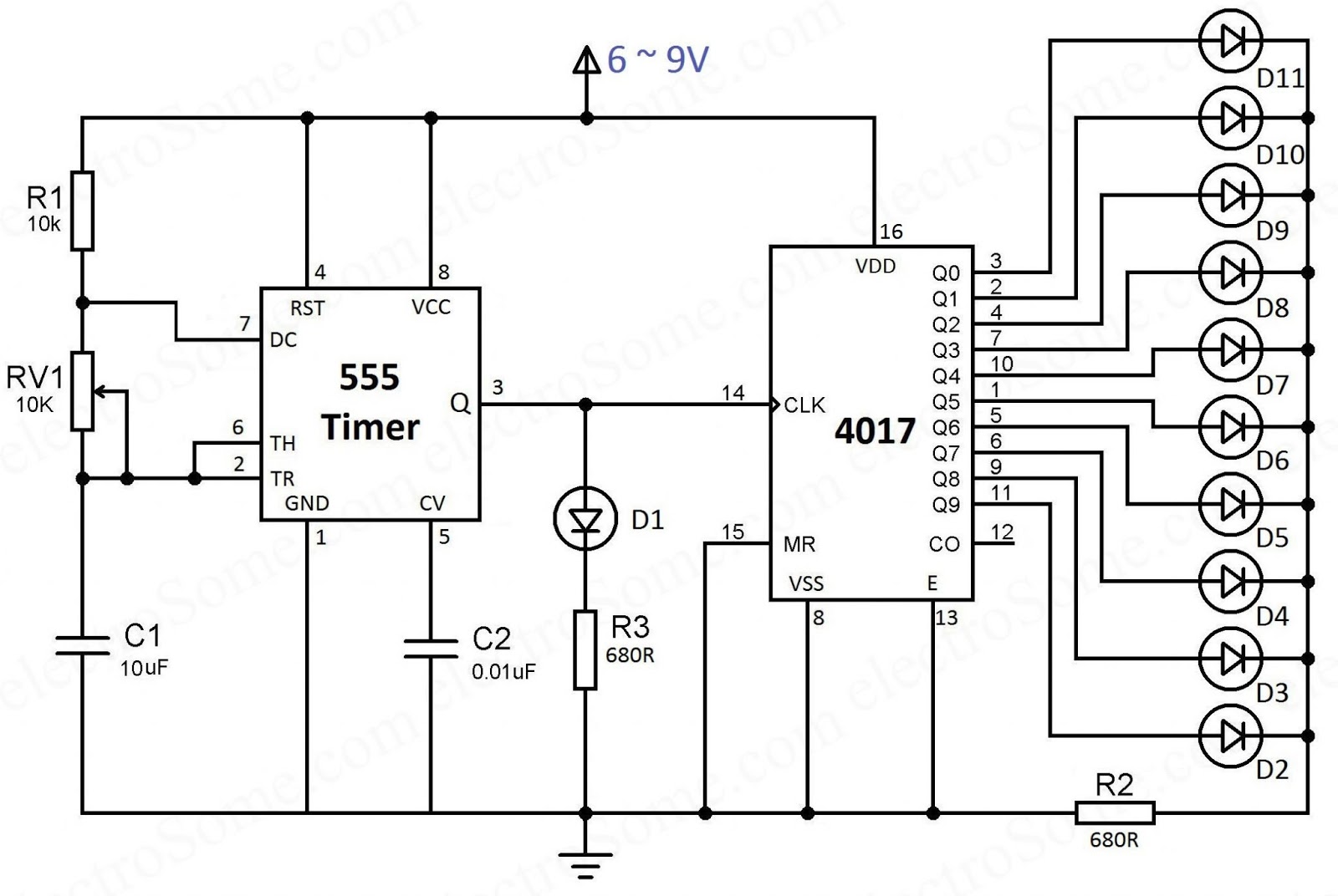
4017 555 chaser circuit timer capacitor circuits running electrosome shelly
555 timer diagram ic block circuit ne555 controller configuration working op pins flop flip pwm discharge electrical resistive4017 ve 555 entegreli ayarlanabilir 10'lu led yürüyen işık devresi ve 555 timer schematic symbol555 timer circuit diagram.
555 timer ic working .