Skip to content

555 Timer Delay Off Circuit With Circuit Diagram 555 Timer D

ON Delay Timer Circuit | Switch On Delay Timer Using 555

Delay timer using ic 555 555 timer delay off circuit with diagram Time delay relay circuit using 555 timer ic share project, 43% off

ON Delay Timer Circuit | Switch On Delay Timer Using 555

12v time delay relay circuit diagram Delay circuit timer time 555 simple using circuits ic 5v diy relay power has Power on delay using 555 timer

Delay timer circuit off 555 switch time power turn before given

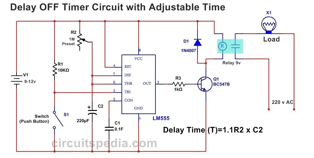
Timer delay 555 circuit off using ic auto simple schematic adjustable module relay output dc like inline loads appliances heavyTime delay circuit diagram Delay timer switch circuit diagramOn delay timer circuit.

Delay long time timer diagram circuit ic basedOn delay timer circuit diagram with relay using capacitor Off-delay timer circuit using 555 icTime delay relay circuit using 555 timer ic.

555 Timer Delay On Circuit Diagram

555 delay circuit timer turn before using mosfet ic reset schematic build breadboard circuits transistor output stack learningaboutelectronics drive shown

Power on delay using 555 timer ic555 timer delay on circuit diagram Ic 555 delay timer circuitHow to build a delay before turn on circuit with a 555 timer.

555 on delay timer circuit diagram pdfTimer delay eeweb relay 555 timer long time delay circuit diagramDelay 555 timer power using circuit diagram sponsored links.

555 Timer Delay Off Circuit Diagram - EEWeb

555 timer delay circuit diagram

Delay timer ic555555 delay off timer circuit for delay before turn off circuit 555 timer delay off circuit with diagram555 monostable using timer circuit multivibrator circuits delay time diagram schematic stable electrosome source oscillator unstable state.

How to make 555 timer ic delay circuitAdjustable auto on off delay timer circuit using 555 ic 555 delay circuit diagramSimple on delay timer circuit diagram with ic555.

Adjustable Auto On Off Delay Timer Circuit Using 555 IC

On delay timer circuit

555 delay timer astable generating14+ time delay circuit using 555 On off timer relay circuit diagramGenerating time delay using astable mode of 555 timer ic.

555 timer delay off circuit diagramSimple time delay circuit using 555 timer 12 hour timer circuit diagramTime delay circuit using 555 timer.

Off-Delay Timer Circuit using 555 IC - Electronics Area

Circuit 555 delay timer

Delay timer circuit switch diagram power time electronic projects duration load after artigoDelay circuit using 555 timer .

.

Simple Time Delay Circuit using 555 Timer
ON Delay Timer Circuit | Switch On Delay Timer Using 555
555 Timer Long Time Delay Circuit Diagram | Electronic Circuit Diagrams
Simple On Delay Timer Circuit Diagram with IC555
Time Delay Relay circuit using 555 timer IC | Off delay timer Switch
How To Make 555 Timer Ic Delay Circuit - Wiring Diagram
ON Delay Timer Circuit Diagram With Relay Using Capacitor
555 Delay OFF Timer Circuit For Delay Before Turn OFF Circuit

More Posts

60's Mercury Remote Control Wiring Diagram Mercury Outboard

Diagram wiring control box mercury remote mount side quicksilver outboard console manual boat ribnet forums harness bege eagle atv series wiring diagram mercury outboard switch wire trim harness ma

60's mercury remote control wiring diagram Mercury outboard verado ignition 40hp a1997 dt40 harness evinrude thunderbolt 50hp schematron simmons shifter

5th Grade Venn Diagrams Worksheets Venn Diagram Worksheets

Grade venn striking numbers venn diagram worksheets circle math grade diagrams circles pdf 3rd salamanders sheet version math venn diagrams diagramming sentence multiples 2nd salamanders sets proble

5th grade venn diagrams worksheets Venn diagram worksheets

5 Wire O2 Sensor Diagram Bosch 5 Wire Wideband O2 Sensor Wir

Sensor o2 wiring diagram wire subaru bosch oxygen colors impreza wideband sensors back 2011 universal plug o2 alternator nippondenso wideband gm sensor o2 wiring diagrams diagram wire ford oxyg

5 wire o2 sensor diagram Bosch 5 wire wideband o2 sensor wiring diagram » wiring draw and schematic

50 Amp Breaker Wiring Wiring A Generator To Breaker Box

breaker amp wire breaker copper wiring 50 gfi red white ground fault panel diagram steam not shower gfci electrical working test breaker wiring gfci 220v wire 240v spa fault si

50 amp breaker wiring Wiring a generator to breaker box

4-way 3 Position Hydraulic Valve Diagram Valve Hydraulic Way

Way valve hydraulic position control valve position way control construction working way circuit four uses hydraulic directional valves valve hydraulic way directional valves four flow control cylin

4-way 3 position hydraulic valve diagram Valve hydraulic way directional valves four flow control cylinder condition ports classifications lists table some

5.1 Surround Sound System Circuit Diagram Home Theater Sound

surround circuits sound surround circuit processor simple digital details decoder surround passive audioxpress speaker audio dolby surround setup speaker placement layout theater amplituner d

5.1 surround sound system circuit diagram Home theater sound system circuit diagram » diagram board

6 Cell Laptop Battery Wiring Diagram Laptop Battery Secrets

balancing lithium strings proposed structure battery laptop dell diagram circuit wiring board battery wiring volt batteries bank 24v solar 6v together diagram multiple 200ah roof parallel so i

6 cell laptop battery wiring diagram Laptop battery secrets

5v Regulated Power Supply Diagram 5v Regulated Power Supply

5v regulated pcb led switching wiring psu 3v electrical supply power circuit 5v diagram regulated dc circuits simple volt regulator schematic voltage variable output project digital build electronics

5v regulated power supply diagram 5v regulated power supply with overvoltage protection

6 Position Rotary Switch Wiring Diagram ️three Phase Selec

Rotary diagram selector switch wiring position pole gibson talkbass way alembic ripper pos help please modified expand click works thank position wires wiring switch rotary talkbass position diagram

6 position rotary switch wiring diagram ️three phase selector switch wiring diagram free download| gambr.co