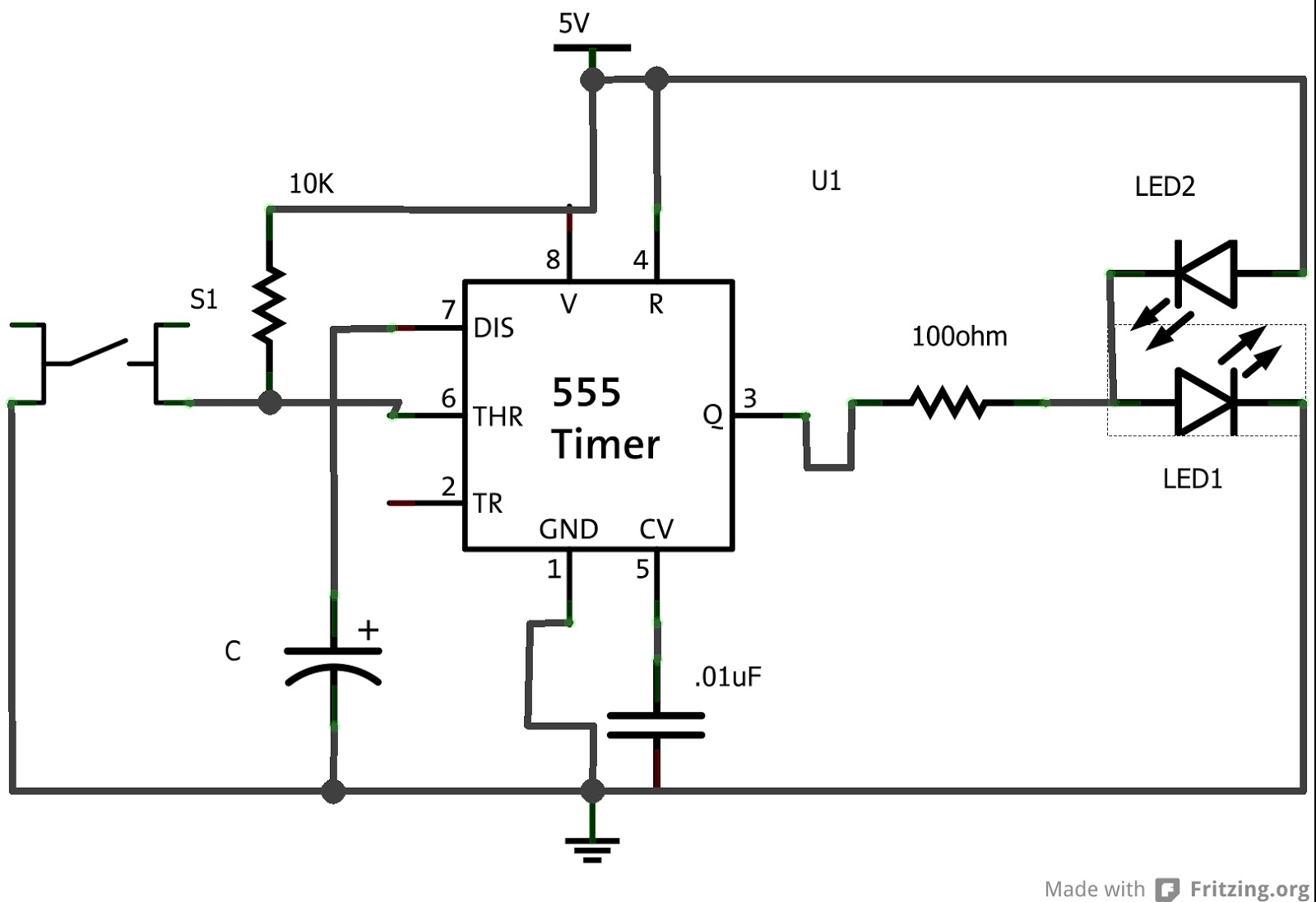
555 Timer One Shot Circuit Diagram One Shot 555 Timer Circui
Timer shot operation basic connected figure output Timer 555 circuits sourcing 555 timer one shot circuit diagram
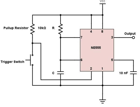
555 Timer Basics - Monostable Mode
Introducing 555 timer ic Timer multivibrator monostable schematic 555 monostable circuits timer shot inspirational schematics nutsvolts ne555 ne556 ufreeonline
How to build 555 timer mono stable (one shot) circuit
Introduction to the 555 timer555 timer circuits schematics one shot Timer 555 second 30 led shot light circuit totally confused strip ltspice share dec stack555 one-shot timer with relay at output.
Monostable 555 timer electronics projects for beginners, hobby555 timer circuit electronics lambert One shot 555 timer schematic / brief 555 timer monostable one shot modeElectronics components: 555 timer chip in monostable (one-shot) mode.

555 timer circuit diagram
10 best timer circuits using ic 555 – homemade circuit projects555 timer one shot circuit diagram 555 timer circuit pin diagramHow does ne555 timer circuit work.
555 one-shot timer with relay at output555 timer schematic : 555 timer delay off circuit diagram 555 timer circuit delay monostable diagram learningaboutelectronics circuits module eewebGe washer timer diagram.

555 timer ic
555 timer one shot circuit diagram555 timer circuits monostable waveform 555 timer one-shot 30 second light led strip, totally confused555 timer basics.
Monostable 555 timer circuit diagramOne shot 555 timer schematic : 555 timer monostable mode one shot Shot 555 timer circuit diagram sponsored links circuitdiagram555 timer circuits blinking example.

Lc meter using 555 timer
555 timer tutorial and circuitsGe washer timer diagram 555 timer circuit ic diagram astable mode tutorial random introducingOne shot 555 timer schematic.
555 one shot timer555 timer ic working 2. demonstrate the use and operation of 555 timers.555 timer monostable circuit diagram variable shot mode led pulse resistor potentiometer basics off time use bistable connect simple clock.

555 timer tutorial and circuits
One shot 555 timer circuit not simulating555 timer one shot circuit diagram .
.