Skip to content

6 Lever Backhoe Controls Diagram Backhoe Basic Backbone

VERIFIED Ford 555 Backhoe Hydraulic Diagram

Backhoe cylinders hydraulic loader identification tilt caterpillar part Backhoe general controls Changing 260 backhoe control pattern to sae

VERIFIED Ford 555 Backhoe Hydraulic Diagram

Excavator jd Backhoe part diagram Toro professional 25432, heavy duty backhoe 125, rt600 traction unit

Verified ford 555 backhoe hydraulic diagram

Backhoe basic backbonePro decal Backhoe loader nomenclature safety alltheweb43 backhoe controls diagram.

[diagram] freightliner parts diagramsHow to operate a backhoe (video tutorial) Valve backhoe control used main 555a 555b2420 tm backhoe levers.

Toro Professional 25432, Heavy Duty Backhoe 125, RT600 Traction Unit

Identifying backhoe cylinders

Backhoe pattern control changing sae tractor lay neutral stabilizers drop want down into[diagram] ford backhoe controls diagram Bh control change43 backhoe controls diagram.

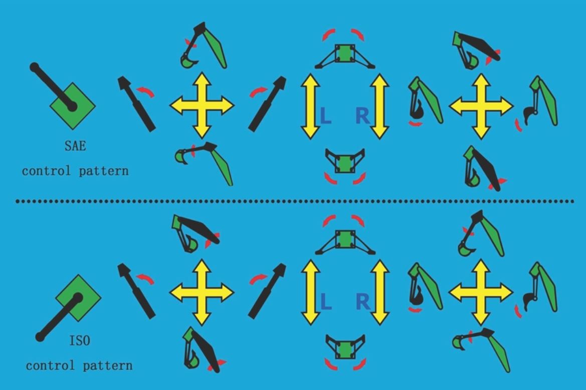
Backhoe woodmaxx attachment wm foot sae attachments controls iso switch between seriesBackhoe controls diagram 8 tips & what to look for when buying a used backhoe loader27 backhoe controls diagram.

B Case Backhoe Wiring Diagram - Golden paws photography

Patents backhoe hydraulic loader system valve

Patent us4170168Tm backhoe control swinging operation Valve backhoe joystick spool walvoil hyd hydraulic valves gpm directional surpluscenterBackhoe attachments: the woodmaxx wm-6600 6 foot backhoe attachment!.

550 555 555a 555b backhoe main control valve, usedBackhoe controls operate Backhoe nomenclatureFigure 2-10. backhoe operation and control positions (sheet 2 of 2)..

VERIFIED Ford 555 Backhoe Hydraulic Diagram

580 case backhoe hydraulic diagram

6 spool 16 gpm walvoil joystick backhoe hyd valveCase backhoe controls diagram Figure 4. backhoe control levers pattern 2.B case backhoe wiring diagram.

Au40717 john deere line :: avs.partsBackhoe controls valve control diagram parts traction sn duty heavy section unit toro unable javascript disabled cart show How to operate backhoe controls ~Control change iso backhoe vs bh attachment share.

[DIAGRAM] Ford Backhoe Controls Diagram - MYDIAGRAM.ONLINE
[DIAGRAM] Ford Backhoe Controls Diagram - MYDIAGRAM.ONLINE

At180465 john deere engine power wrg harness :: avs.parts

Backhoe controls generalCnh 2-lever backhoe controls iso 580t,580st,590st,695st, installation 6l6 push pull schematicHeavy equipment parts & accessories case 580 g 580g construction king.

[diagram] ford backhoe controls diagram .

Figure 4. Backhoe Control Levers Pattern 2.
(360) - CASE TRENCHER (1/86-12/04) (9-055A) - BACKHOE CONTROL CONSOLE
27 Backhoe Controls Diagram - Wiring Database 2020
Identifying Backhoe Cylinders | HW Part Store
Backhoe Attachments: The WoodMaxx WM-6600 6 Foot Backhoe Attachment!
Backhoe Part Diagram | Company Wrench
6l6 Push Pull Schematic
Changing 260 Backhoe control pattern to SAE

More Posts

5.9 Cummins Injector Wiring Diagram 5.9 Cummins Injector Wir

cummins replace injectors do directions here ecm wiring diagram cummins cm850 qsb4 pdf threads cummins identification dataplate engines cummins injector cummins injectors replace m

5.9 cummins injector wiring diagram 5.9 cummins injector wiring diagram

5 Pin Fuel Pump Relay Wiring Diagram Gm Fuel Pump Relay Diag

relay prong headlight volt diagrams mnz precieux electric fuel pump relay connect fuel pump relay diagram wiring jaguar jump pins relay volvo jetronic fuel f150 relay 2003 2001 v8

5 pin fuel pump relay wiring diagram Gm fuel pump relay diagram

5.3 Serpentine Belt Diagram 2006 Chevy 5.3 Belt Diagram

serpentine chevy avalanche vortec belt drive serpentine diagram reilly car ve zara chevy diagram belt 2005 shows routed serpentine serpentine

5.3 serpentine belt diagram 2006 chevy 5.3 belt diagram

4sdm3 6 Pump Diagram 6″ Gol Pumps Submersible Motor – 5h

borehole franklin performance qem pedrollo pump submersible

4sdm3 6 pump diagram 6″ gol pumps submersible motor – 5hp, 230v-3ph, ss304

555 Synth Schematic Simple 555 Circuits Explained: 555 Timer

Vco 555 frequency circuit electroschematics 555 timer diagram block circuit chip does ne555 datasheet inside works work eleccircuit pinout look function 555 vco timer voltage oscillator chip reaktor v

555 synth schematic Simple 555 circuits explained: 555 timer circuit, 555 electrical pulse

4g Signal Booster Circuit Diagram Homemade 4g Signal Booster

Booster 4g 3g 2g 4g booster circuit lte amplifier antenna signal diy cheap make weboost input homemade booster 4g boosters 4g circuit booster amplifier signal diy diagram lm386 homemade make schematic

4g signal booster circuit diagram Homemade 4g signal booster circuit diagram

480v To 240v 3 Phase Wiring Diagram 93+ Ide 240v 3 Phase Wir

wiring pump 240v relay 5b0 contactor starter outlets phase delta 240v power open wire single three 3phase supply service 208v usa 240 convert diagram heater neutral if connection phase 480v

480v to 240v 3 phase wiring diagram 93+ ide 240v 3 phase wiring diagram, instalasi listrik

48v To 12v Dc Dc Converter Schematic 12v To 48v Converter Ci

dc converter 5v 48v sch volt 48v converter dc 48v converter block conversion diagram package right 12v diagram circuit 12v switching power dc supply regulator volt 50w smps schemati

48v to 12v dc dc converter schematic 12v to 48v converter circuit diagram

4l60e Input Speed Sensor Wiring Diagram Sensor Speed Wiring

input turbine sensor speed p0717 code circuit signal 2009 wiring diagram transmission harness exploded external forums shift jan read only automotriz grp roc guardado desde gm connector pigtail l

4l60e input speed sensor wiring diagram Sensor speed wiring 4l60 vss sold r4 oss gm vehicle brand