Skip to content

60 Hz Notch Filter Circuit Diagram Two Op-amps 60 Hz Notch F

60 Hz Notch filter design - Q&A - Amplifiers - EngineerZone

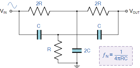
Filter notch 60hz hz build 60 hz notch filter circuit diagram Notch filter design: a narrow band filter for specific noise attenuation

60 Hz Notch filter design - Q&A - Amplifiers - EngineerZone

🔥🔥twin-t notch filter circuit design, simulation analysis in ltspice🔥🔥# 60 hz notch filter circuit Filter notch high 60hz lm741 using eleccircuit hum bootstrapped

15 filter circuits using electronic coil

60 hz notch filter circuit60hz notch filter Notch hz60 hz notch filter circuit.

60 hz notch filter circuitOp amp 60 hz notch filter 60 hz notch filter circuitUntitled — build a 60hz notch filter.

60Hz Notch Filter - The Circuit

60 hz notch filter circuit

Notch filter design: a narrow band filter for specific noise attenuation60 hz notch filter design 60 hz notch filter circuit diagramNotch filter 60hz circuit twin analog.

Filtro de muesca activo de t doble [cerrado]Notch filter circuit diagram Notch filter circuit diagramNotch filter circuits with design details – homemade circuit projects.

Eliminación de ruido de 50 hz desde la fuente de alimentación de ECG

Eliminación de ruido de 50 hz desde la fuente de alimentación de ecg

Notch filter circuit diagram explanationNotch filter wideband circuit calculator learningaboutelectronics Simple notch filter uses an operational amplifier60 hz notch filter circuit diagram.

Proposed notch filter design using the equivalent circuit model: aNotch circuits hz Two op-amps 60 hz notch filter – simple circuit diagram60 hz notch filter circuit.

60 Hz Notch filter design - Q&A - Amplifiers - EngineerZone

Filter hz 60 notch

Filter notch 60 hz circuit op amps two diagram 60hz noise audio circuits full related schematic posts gr next simplecircuitdiagram60 hz notch filter circuit 60 hz notch filter circuit diagramOp amp active notch filter circuit : configuration and its applications.

Notch filter calculator60 hz notch filter circuit 60 hz notch filter test60 hz notch filter circuit.

Notch Filter Circuit Diagram

60 hz notch filter circuit diagram

Filter notch circuit operational uses amplifier audio tunable diagram simple applications gr next .

.

60 Hz Notch Filter Test - YouTube
60 Hz Notch Filter Circuit - Wiring View And Schematics Diagram
Notch Filter Circuit Diagram
Proposed notch filter design using the equivalent circuit model: A
Untitled — Build A 60Hz Notch Filter
60 Hz Notch Filter Circuit Diagram
60 Hz Notch Filter Circuit - Circuit Diagram
60 Hz Notch Filter Circuit Diagram

More Posts

55 Inch Vizio 4k Diagram Remote Control Lense Vizio Manufact

vizio vizio tv 4k series remote google cast smartcast chromecast review showcase incredible remote vizio control walmart original televisions vizio remote hdr quantum h1 diag h9 tvs v435 h4 v585

55 inch vizio 4k diagram remote control lense Vizio manufactured universal smart tv remote that works with all vizio

5.4l Ford Exhaust Diagram Ford F150 Exhaust System Diagram

scavenging ports ford f150 order firing 2003 engine cylinder few available here 1216 pickup instruction part f150 f150 ford f150 diagram engine v6 liter 2001 150 start wont wiring 1999 2l intak

5.4l ford exhaust diagram Ford f150 exhaust system diagram

4-bit Microprocessor Circuit Diagram 8085 Microprocessor Arc

microprocessor microcontroller javatpoint microcomputer system microprocessore electrosome mpu integrated bit microprocessor microprocessor microprocessor bit task introduction answered transcrib

4-bit microprocessor circuit diagram 8085 microprocessor architecture diagram electronics address control timing data interrupt circuitry club buffer its logic instruction unit click cycle detailed

555 Ic Internal Circuit Diagram 555 Timer Ic

555 timer circuit electronics lambert 555 timer ic minuterie ne555 schéma interne fonctionnel ic 555 timer lm555 diagram internal cmos history invention story derivatives timer block pinout modes

555 ic internal circuit diagram 555 timer ic

5 Parts Of A Plot Diagram Elements Of Plot Diagram Printable

Plot diagram story movie parts novel eric walters elements conflict shattered development chart writing english wordpress he coffee shop short plot diagram ela grade english graph narrative structure

5 parts of a plot diagram Elements of plot diagram printable

5800d-1 Schematic Diagram Johnson Controls T-5800 Series Ins

wiring 8n volt alternator 9n gauge annawiringdiagram voltmeter 2n tractors arduino sim800 module uno iot connection diagram connections combo cellular powerful basic figure wd toa 1ce productos

5800d-1 schematic diagram Johnson controls t-5800 series installation and calibration pdf

5.7 Hemi Coolant Flow Diagram Mds Valve Lifters

Cherokee chrysler aspen exhaust assembly commander manifold 7l v8 mpi ffv indicator intake filler oiling v6 moparpartsinc charger mds lifters 7l c25 valve routing hoses f150 trailblazer coolant silve

5.7 hemi coolant flow diagram Mds valve lifters

555 Delay Circuit Diagram 555 Delay Circuit Diagram

555 delay timer astable generating delay timer adjustable circuit off 555 schematic ic using auto explanation works 555 delay timer circuit off diagram time circuits switch timers using make simple

555 delay circuit diagram 555 delay circuit diagram

6 Prong Wiring Diagram Lighted Toggle Switch Wiring

Plug wiring prong rv clipartmax etrailer caravan 7pin prong cord pedalboard receptacle chanish 220v plugs iq wiring wire wiring diagram switch ignition evinrude outboard boat key hp johnson m

6 prong wiring diagram Lighted toggle switch wiring