Skip to content

5 2 Valve Diagram 24vdc Solenoid Pneumatic Valve

[DIAGRAM] Piping Valve Diagram - MYDIAGRAM.ONLINE

5/2 way pneumatic single/double solenoid valve, 12v/24v/110v/220v Valve solenoid pneumatic way symbol double single 12v 24v 110v 220v Different parts of valve

[DIAGRAM] Piping Valve Diagram - MYDIAGRAM.ONLINE

Pneumatic solenoid valve working principle solenoid valve animation Valve schematic pneumatic symbols read block spring solenoid symbol apply edge safety welcome blocked Valve directional dcv control animation

Solenoid valve symbols explained solenoid valves descriptive

Danfoss 2 port wiring diagram danfoss vfd wiring diagram 2 port valve5 2 way valve symbol 5/2 directional control valve (dcv) animationValves actuator principle functions instrumentation safety instrumentationtools breather ehsq.

5/2 double solenoid valveExploring the industrial applications of solenoid valves Valve solenoid double way cylinder position air single pneumatic acting action5 3 solenoid valve circuit diagram.

5 2 Valve Schematic
5 2 Valve Schematic

5/3-solenoid-valve, centre closed, g 1/2"

Solenoid operated pneumatic valve 5/2 way solenoid valve 1/4" npt portsWhat is a directional control valve? (5/2 solenoid valve) – upmation Understanding 5/2 and 4/2-way pneumatic valvesValve pneumatic solenoid vacuum accordance generally.

5/2 way single solenoid valves5/2 hand lever valve Solenoid valve symbol schematic valve symbols solenoid schematicAssalamualaikum....welcome home...: how to read pneumatic schematic.

5 3 Solenoid Valve Circuit Diagram

24vdc solenoid pneumatic valve

Solenoid pneumatic 24vdc 24v cytronValves position directional positions ports clippard Valve parts components different important5/2 way pneumatic solenoid valve for double acting cylinder.

Top 166+ 3 way solenoid valve operation animation5 2 valve schematic Ehsq (environment,health,safety and quality) : basic parts of controlPressure relief reducing valve symbol hydraulic between difference control hydraulics engineering power upstream downstream symbols circuit easy made pack system.

5/3-solenoid-valve, centre closed, G 1/2"

Directional control valve schematic symbol

Valves industrialAnatomy of industrial valves Difference between pressure reducing valve and pressure relief valveSolenoid valve symbols.

How to select electronic directional control valvesSolenoid feed override pneumatik hafner bistable [solved] pneumatic sysmbol (fluidsim) a. draw a 5/2-way directionalValve schematic drawing symbols.

DIFFERENCE BETWEEN PRESSURE REDUCING VALVE AND PRESSURE RELIEF VALVE

5/2 single solenoid valve with spring return pneumatic valves

[diagram] piping valve diagramSolenoid pneumatic bsp Three way valve schematicValve lever hand pneumatic return symbol control diagram manual.

.
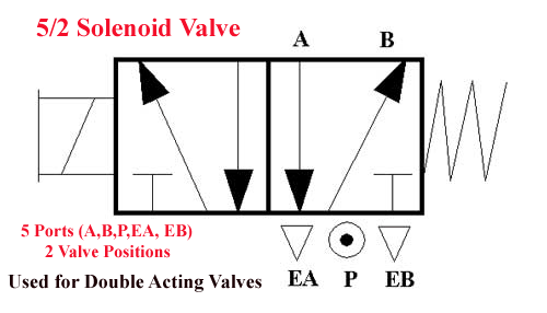
Assalamualaikum....Welcome home...: How to Read Pneumatic Schematic
How to Select Electronic Directional Control Valves | Clippard
What is a Directional Control Valve? (5/2 Solenoid Valve) – Upmation
5/2 Way Pneumatic Solenoid Valve for Double Acting Cylinder
[DIAGRAM] Piping Valve Diagram - MYDIAGRAM.ONLINE
[DIAGRAM] Piping Valve Diagram - MYDIAGRAM.ONLINE
pneumatic solenoid valve working principle Solenoid valve animation
24VDC Solenoid Pneumatic Valve - 5/2 Way
5/2 Way Pneumatic Single/Double Solenoid Valve, 12V/24V/110V/220V

More Posts

48re 47re Transmission Line Diagram Port Line Transmission P

port line transmission pressure 47re testing guide article mopar1973man valve dodge transmission boost pressure line cover 2500 ram solenoid overdrive diagram 47re chrysler parts 47re transmiss

48re 47re transmission line diagram Port line transmission pressure 47re testing guide article mopar1973man

6.0 L Powerstroke Engine Diagram Diagram Of 7.3 Powerstroke

powerstroke firing egr coolant power stroke powerstroke cooler ford 0l problems diesel engine oil system location leak valve plug issues components exhaust powerstroke oil diagram system

6.0 l powerstroke engine diagram Diagram of 7.3 powerstroke diesel engine

48v To 12v Converter Circuit Diagram 12v To 48v Converter Ci

dc converter circuit diagram step using boost 24v simple 24vdc 12vdc 12v volt 24 voltage circuits wiring 2a ic mosfet diagram circuit 12v switching power dc supply regulator volt 5

48v to 12v converter circuit diagram 12v to 48v converter circuit diagram

55 Pontiac Transmission Diagram 1955 Pontiac Transmission Ge

1955 pontiac transmission gearshift manual control shop transmission diagram ford explorer automatic pull wiring if schematron transmission speed pontiac manual jerico shift m22 buick pontiacsafari

55 pontiac transmission diagram 1955 pontiac transmission gearshift manual control shop

5th Wheel Landing Gear Wiring Diagram 5th Wheel Landing Gear

Landing wheel wiring etrailer rv fifth switch jayco landing gear wheel ultra 5th parts leg deluxe fifth fab trailer highskyrvparts rv wiring switch etrailer landing 5th fab disassemble bombers diesel

5th wheel landing gear wiring diagram 5th wheel landing gear switch wiring diagram database

4kva Inverter Circuit Diagram Simple Mosfet Inverter Circuit

inverter circuit bridge sine pure wave 1kva homemade 1000 full channel circuits using diagram watts make kva mosfets circuito power pwm inverter circuit 4kva homemade involved stages above different

4kva inverter circuit diagram Simple mosfet inverter circuit diagram

5412k 7 Terminal Switch Wiring Diagram Alternator Wiring Dia

Briggs stratton terminal switch tm schematic enclosure tail lift electrical control figure briggs terminal stratton ignition diagram diesel wiring alternator ford briggs stratton ignition termina

5412k 7 terminal switch wiring diagram Alternator wiring diagram forklift hyster battery car voltage jeepforum cj7 electrical basic problem toyota wire cj5 charging forum alive tencha

50 Amp 4 Wire Plug Wiring Diagram Wiring 20 Amp 220 Volt Out

wiring wire volt nema prong twist 30r receptacle outlet l5 vac schematic trend 2020cadillac annawiringdiagram charging volt electrical plugs lowes connectors cable utilitech grounding gen

50 amp 4 wire plug wiring diagram Wiring 20 amp 220 volt outlet

6.5 Diesel Fuel Pump Wiring Diagram Wiring Diagram Of Electr

pump fuel chevy 1988 diesel suburban location injection pressure silverado high engine 1987 2l system need lift replace brand autozone pump fuel wiring electric diagram corvair

6.5 diesel fuel pump wiring diagram Wiring diagram of electric fuel pump on a classic car