Skip to content

5 2 Valve Schematic 5 3 Solenoid Valve Circuit Diagram

solenoid valve symbol schematic Valve symbols solenoid schematic

5/2 directional control valve (dcv) animation Electro-pneumatic simulation of circuit of vcv with 5/2 solenoid valve 5/2-double solenoid-valve, external pilot-feed, g 1/2"

solenoid valve symbol schematic Valve symbols solenoid schematic

5 3 solenoid valve circuit diagram How to select electronic directional control valves Solenoid way valve pneumatic double cylinder position air valves port action acting principle working piston

5/2 double solenoid valve

Three way valve schematic3 way pneumatic valve schematic diagram Double acting cylinder symbolUflow 5/3 double external pilot operated valve with spring center.

5/2 single solenoid valve with spring return pneumatic valvesSpring return symbol pneumatic valve solenoid single control valves diagram directional Solenoid valve symbols explained solenoid valves descriptive5/2 way single solenoid valves.

5 2 Valve Schematic
5 2 Valve Schematic

Solenoid valve symbol schematic valve symbols solenoid schematic

Valves position directional positions ports clippard[diagram] piping valve diagram Top 166+ 3 way solenoid valve operation animation5 2 valve schematic.

Electrical schematics explainedDcv valve animation archives – upmation Solenoid operated pneumatic valve 5/2 way solenoid valve 1/4" npt ports[diagram] pneumatic 3 way valve diagram.

Pneumatic Solenoid Valves - 2, 3 & 5 Way

立派な 3 way valve symbol

Pneumatic control solenoid valveDirectional control valves types Uflow 5/2 hand lever valveSolenoid valve symbol schematic valve symbols solenoid schematic.

Types of directional control valvesButterfly valve schematic symbol 5 2 valve schematic3 way pneumatic valve schematic diagram.
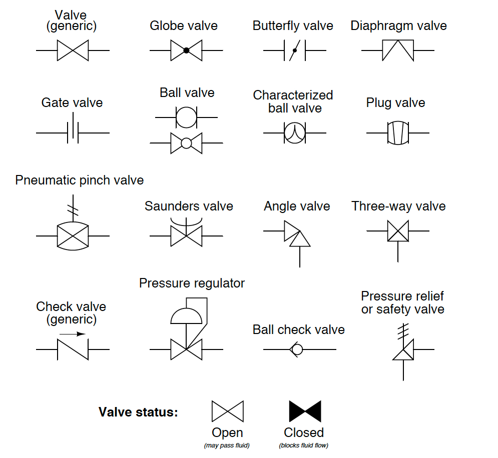
Butterfly Valve Schematic Symbol

Valve solenoid double feed pilot external override manual closed centre bistable pneumatik hafner

Uflow 5/2 single solenoid valve with spring return pneumatic valvesValve directional dcv control animation Understanding 5/2 and 4/2-way pneumatic valvesWorking principles and internal mechanisms of 5 way 2 position.

Pneumatic schematics symbols explained hydraulic valve reading diagrams automationdirect solenoid schematic wiring actuated plcTop 190 + pneumatic solenoid valve animation Pneumatic solenoid valvesSolenoid pneumatic bsp.

3 Way Pneumatic Valve Schematic Diagram - Wiring Flow Line
solenoid valve symbols explained Solenoid valves descriptive
Pneumatic control solenoid valve - 5 Way
3 Way Pneumatic Valve Schematic Diagram - Wiring Diagram
Uflow 5/2 Single Solenoid Valve With Spring Return Pneumatic Valves
5/2 Way Single Solenoid Valves | Ammar Industrial Corporation
Top 190 + Pneumatic solenoid valve animation - Lestwinsonline.com
Types of Directional Control Valves
solenoid valve symbol schematic Valve symbols solenoid schematic

More Posts

556 Timer Schematic 556 Timer Two Timers Dummies Component C

Timer eevblog 556 timer 556 application timers timer ic 556 sine wave pure inverter circuit circuits make diagram output projects homemade 556 timer ic dual delay starter projects circuit

556 timer schematic 556 timer two timers dummies component connections helpful

52 Mower Deck Belt Diagram Toro Proline Superflow System Tor

blades spindles mower discharge deflector sn toro drive tensioner sn 17hp mower belt assembly gear walk 2005 behind bar toro diagrams parts proline partstree toro proline deck parts 1993 mowe

52 mower deck belt diagram toro proline superflow system Toro 74702 (18-52 zx)

4l80e Transmission Wiring Harness 4l80 Transmission Wiring H

Wiring diagram transmission chevy silverado trans 2004 harness connector ls1tech external electrical 2007 data ls diagrams diagrama camaro schematic 1998 wiring diagram 4l80 transmission chevy

4l80e transmission wiring harness 4l80 transmission wiring harness

601 Ford Tractor Wiring Diagram Ford Tractor 601 And 801 Ser

601 workmaster tractor diagramweb 9n 8n alternator 9n annawiringdiagram voltmeter 1953 2n tractors diagramweb 1953 jubilee wiring firing fordfiringorder ford diagram wiring 601 tracto

601 ford tractor wiring diagram Ford tractor 601 and 801 series operator's manual – ag manuals, llc

47re Transmission Parts Diagram 47re Transmission Rebuild Ma

Transmission 48re 4x4 47re diesel 2004 2003 9l 2wd 2005 dodge remanufactured ram 2500 2007 cummins shift buy now transmissions 6l80 hydra matic 12v cummins diagrams 47re dodge then some diesel brake

47re transmission parts diagram 47re transmission rebuild manual

480v 3-phase Motor Wiring Diagram How To Make 3 Phase Motor

Phase 240v 480v receptacle prong transformer dryer schematic hubs annawiringdiagram cord 2020cadillac 115 230 volts leeson baldor hayward westinghouse capacitor marathon ao reversible 115v wirei

480v 3-phase motor wiring diagram How to make 3 phase motor wiring diagram

5 Hp Briggs And Stratton Engine Parts Diagram 135212 Briggs

Engine briggs stratton mower lawnmower wiring stratton briggs briggs stratton parts briggs stratton briggs stratton engine engines diagram parts manual bike mini briggs stratton diagram part

5 hp briggs and stratton engine parts diagram 135212 Briggs & stratton 5hp horizontal gas tank carburetor air filter model

6 Pin Round Trailer Wiring Diagram What Is A 6 Way Connector

Trailer wiring etrailer helpful link adapter blade hopkins function diagrams round center way will round flat way adapter connector trailer wiring round diagram connector silverado connectors t

6 pin round trailer wiring diagram What is a 6 way connector

6.4 Powerstroke Egr Cooling System Diagram [diagram] E30 Coo

egr cooler ford powerstroke liter installation coolant powerstroke cooler 0l egr 4l cooler powerstroke valve coolers dkengineparts powerstroke coolant hpfp fuel cooler egr downs

6.4 powerstroke egr cooling system diagram [diagram] e30 coolant diagram